Front End
Back to Main Pictures Page
Home
Before installing the front end components you need to first rivet the F-panel to the frame.  This being the first time that I have ever riveted something, I was a little apprehensive about the operation.  This turned out to be a lot easier than it looked. 
I marked the holes in the aluminum then drilled the panel on a piece of wood.  I then mounted the aluminum to the frame using the clecko pins in the holes that were already there from the factory.  I then drilled through the aluminum holes and the frame.   I started riveting with my manual riveter that I bought from Sears.  I didn't think that it was too hard to use.  I then tried my air riveter with the air compressor.  It took absolutely no effort to put the rivets in with it.  I was quite pleased with the results.  Oh yeah, I did put the silicone under the panel before riveting but AFTER the drilling.  (You don't want metal flakes under the panel)
Installing the front end components took quite a bit of prep to get it to this completed state.  Some of the interim tasks that I had to accomplish included:
Cutting the notch in the lower control arms so the shock fits
Replacing the boot for the lower control arm ball joint
Ordering bolts through Breeze Automotive since my pallet donor had the wrong lower control arm bolts
Grinding down the bottom of the lower control arms to make them fit the frame without rubbing against the round tubes


I installed the control arm using the offset aluminum bushings from Breeze Automotive.  According to Mark Reynolds, these bushings will help correct the bump steer problem that is so prevalent with this setup.  He also mentioned that the bump steer kit from FFR really only solves part of the problem.  The key is get the proper angle betweent the steering rack and the spindle (which is what these new bushings do).  This should be 90% of the solution and the FFR bump steer kit finishes the last 10% (according to Mark). 
One thing that you will have to do is drill or file the holes to make the aluminum bushings fit.  There is no play like with the rubber bushings and the holes do not line up exactly.

The FFR manual states that you should screw the tie rod ends all the way to the end of the threaeded arms.  I did this but they were still too long, causing the spindles to not align properly.  I decided to cut the tie rod ends and the steering rod using my angle grinder to make them fit. 
Here is a picture of the completed front end after I installed the brake rotors and calipers.  I purchased brand new rotors, bearings and seals.  I also exchanged my calipers for rebuilt ones. 
Mounted the tires and rims to find that there is significant negative camber.  Went to the cobra forum to try and figure out what the problem is.  I'll have to get this fixed. 
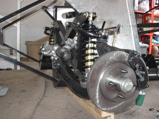
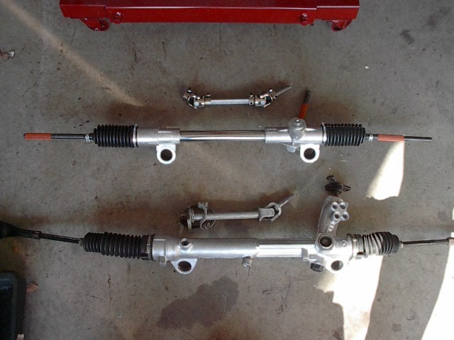
I ended up getting a new (used) set of lower control arms and spindles from Greg Warden down in VA Beach.  That solved the problem with the negative camber.  I think that the parts I had were from a 94+ vehicle because I later found out that the wheelbase is a little wider for the newer cars.  Also because of the wider wheelbase, I ran into a problem with the toe in with the steering rack length.  I decided to bite the bullet and get a flaming river 18:1 manual steering rack setup.  BUY THIS SETUP!  The steering response is so much smoother and easier than the power rack with the power cut out of it.  I also feel more comfortable knowing that my steering setup won't fail me.